JKOwners Forum banner

JK front door panel disassembly guide

163K views 65 replies 41 participants last post by  Big Pappy  
#1 ·
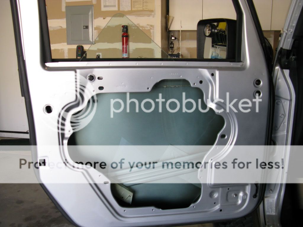
This is a guide for disassembling the JK front driver side door panel. I have a 2008 Wrangler Unlimited Rubicon with power windows. The passenger side should have the same procedure. According to the JK service manual, the rear door procedure is very similar except you have to remove the pillar trim panel to disconnect the wire harness.

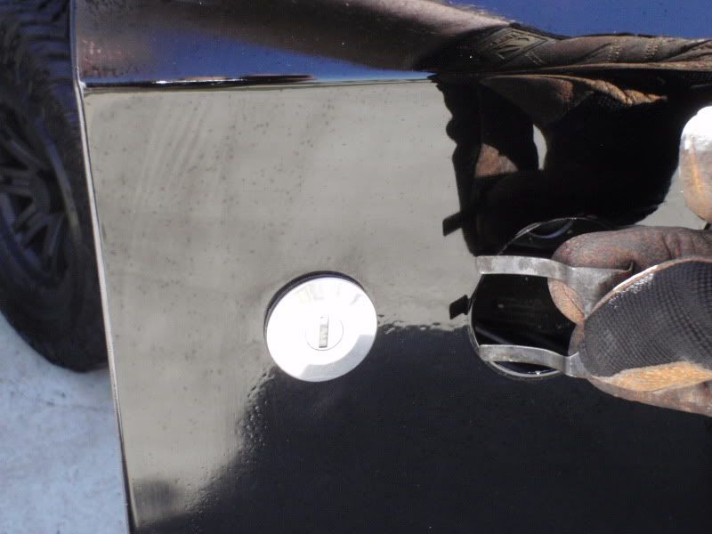
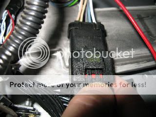
Position the glass into the down position leaving exposed just enough to grasp. Remove the door wiring connector from under the dash. This is done by removing the small red plastic slider then depressing the back of clip as you pull. Reinsert the red plastic slider; it does not have to be removed to snap the connector back on. If you have manual windows, using a standard window handle tool, release the handle clips and remove the handle.


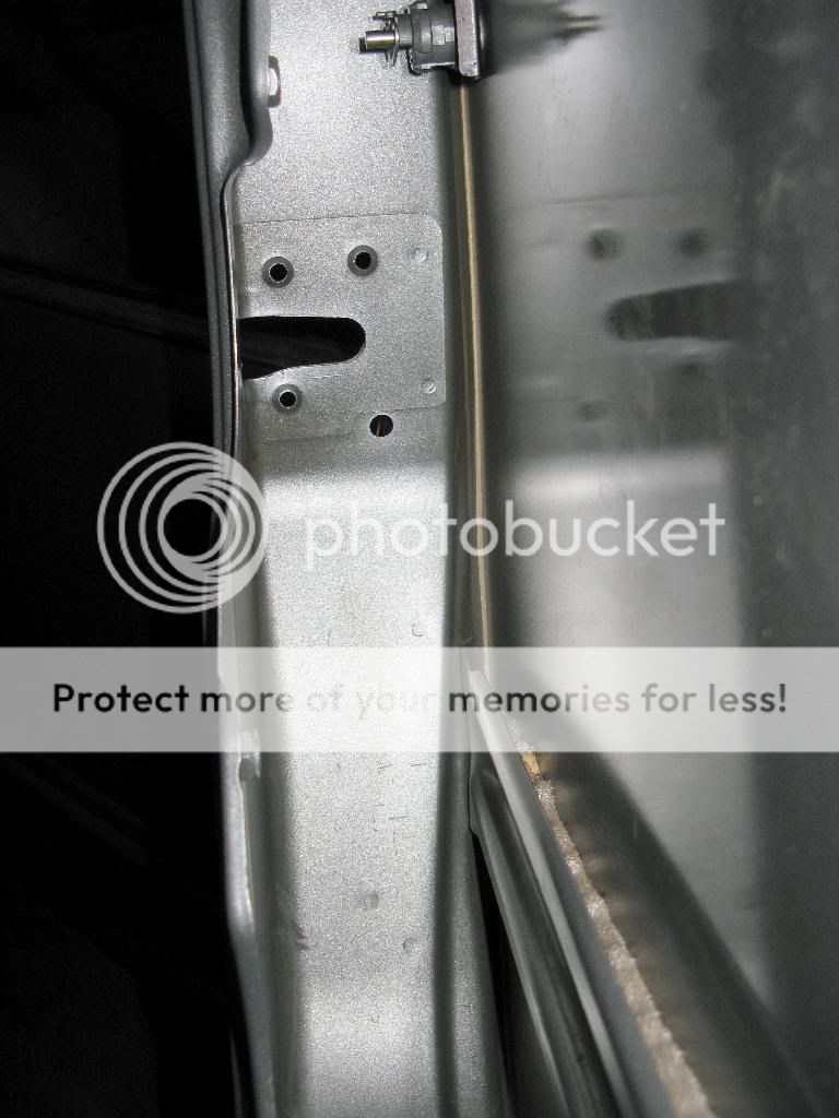
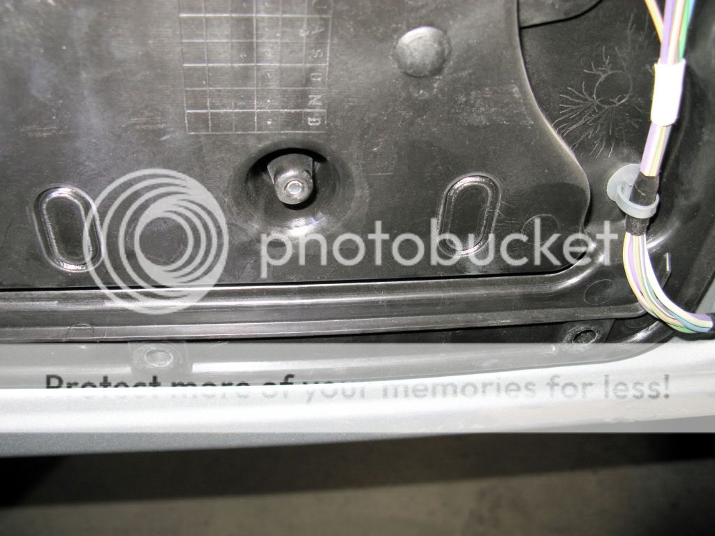
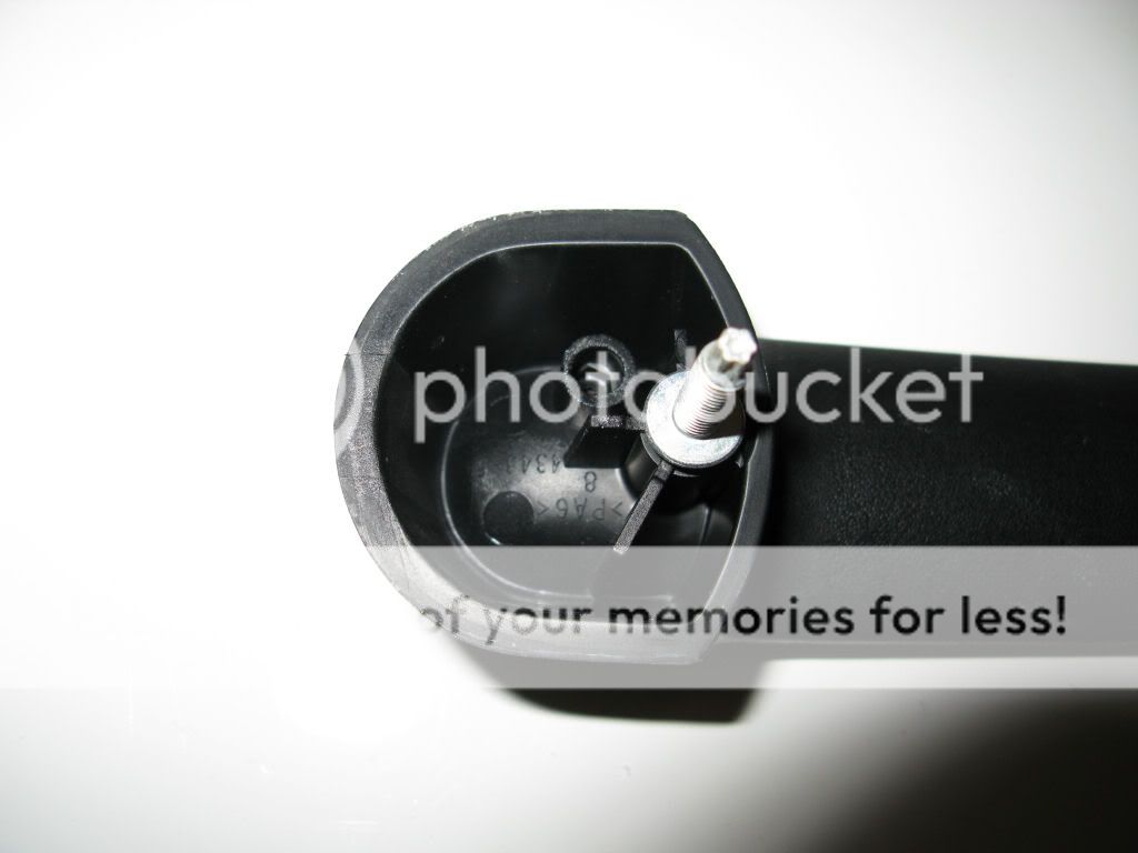
Remove the pull handle trim plugs (not present on my 2008 Rubicon) and remove the pull handle screws. Remove the two screws near the corner that has the check strap.

 
#2 ·
Remove the door trim panel. It is held in place by seven pushpins on back of the panel. Start at the bottom by the check strap and work around pulling on the panel until the pins release. Using a flat pry bar or long screwdriver by each pin may help. The top of the trim panel is slightly over the door edge and lift up to release. Release the power window wiring connector and remove the trim panel.


The carrier plate has two small areas that must be cut out to reach the glass retainer release tabs. Release the two tabs by pushing gently on them with a screwdriver blade while pulling the window up. When later reassembling the door, tape over the hole on the back and front with the cut pieces in-between.

 
#3 ·
Tape the glass to secure in the full up position. Remove the door handle screw. Remove the rubber hole plug in the door and remove the nut.


Remove the upper latch bracket screw. Remove the three latch screws.


Separate the check strap from the hook, remove the screws, and separate the wire harness from the door. Remove the ten carrier plate screws and remove the carrier plate assembly from the door.
 
#4 · (Edited)
Carefully remove the tape and lower the glass into the door. Turn the glass so the front of the glass is facing down. Lift up and remove the glass through the glass opening. For reassembly just reverse these steps.


Here is the installation procedure with torque settings from service manual:

1. Place the latch assembly into the door opening and install the carrier plate (7) onto the door.
2. Install the latch screws (4) and tighten to 8 N·m (71 in. lbs.) top screws first.
3. Install the latch bracket screw (3).
4. Install the 10 carrier plate screws (5) and tighten to 10 N·m (90 in. lbs.).
5. Install the outside door handle nut (2) through the hole in the inner door and tighten to 4.5 N·m (40 in. lbs.).
6. Install the inside door handle screw (1) and tighten to 8.5 N·m (75 in. lbs.).
7. Slowly lower the glass (1) all the way down into the regulator lift plate (3) and seat the glass clip (4) fully until a snap sound is heard.
8. Seal the glass disconnect holes with a suitable foam tape or equivalent.
9. Install the trim panel (1), (Refer to 23 - BODY/DOOR - FULL FRONT/TRIM PANEL - INSTALLATION).
Image
 
#8 ·
I tipped into a rock and had to pound the dent out.

Also someone wanted to sound insulate their doors but couldn't figure out how to get it off. The razor knife work at the end of the 2nd post is what they needed.

It looks like he is moving his write ups from jk-forum. Dont ask why say thanks you never know when you might need this info and when you search for it you shall find.
LOL- I understand why some of these you might think came from WayofStrife's forum . I am moving from jkboard though.
 
#16 ·
I had a request about replacing the lock cylinder. I have never done it, here is what the service manual says:

Removal
1. Remove the carrier plate, (Which is what my posts above are doing)
2. Remove the clip (3) and separate the lock cylinder (2) and gasket (1) from the door.

INSTALLATION
1. Assemble gasket (1) onto lock cylinder (2) until fully seated.
2. Install lock cylinder (2) into hole in outer door panel.
NOTE: Cylinder post must point forward.
NOTE: Cylinder drain hole must point down.
3. While holding lock cylinder (2) in place slide retainer clip (3) onto lock cylinder.
NOTE: Visually verify that pin on lock cylinder is engaged with bell crank 0n door module at door module install.

Image
 
#17 ·
Seems to be the season for door problems.

Detail on the door handle. After removing the carrier plate above, remove the front nut and it comes right off. When reinstalling, if you want to follow the service manual, the torque spec is 4.5 N·m (40 in. lbs.).


BTW, most of my posts you can click on the pictures for a larger pic.


#18 ·
Seems to be the season for door problems.

Detail on the door handle. After removing the carrier plate above, remove the front nut and it comes right off. When reinstalling, if you want to follow the service manual, the torque spec is 4.5 N·m (40 in. lbs.).
Thanks! I have a replacement handle so I'm quite familiar with one, but wasn't aware of the torque spec. I am in the process of fabbing some low-profile stainless steel replacements, but.... expensive endeavor. Hopefully by the new year.
 
#27 ·
I'm not even sure how a dog could shit onto a vertical surface - was this after you rolled the jeep and scared the shit out of the dog?
 
#22 ·
Here is the last of it - inside door shots. This has turned out to be more needed than I expected.

I edited my post above to include service manual installation procedure with torque settings.


#29 ·
Wanted to add a little for those with half doors or those who want to get the lock assembly out.

The half doors are very simple to take apart, you only need two sizes of Torx (T27/T40), a cross tip / phillips screw driver and a 8mm driver or socket.

Image


There are only three screws (all phillips) in the door panel, two on the handle and one in the middle of the pocket on the bottom.

Image


Once those are removed you can give the panel a good tug and it will pop right off.

Image


Once the panel is off there are two screws that hold the inside handle assembly in place:

Image


The outside door handle is held on by two bolts (same as the full doors), both are accessible from holes in the door metal

Image


Image


One difference between the front and the back outer door handle removal is that on the rear doors is that you have to remove a little rubber plug to get to one of the outer door handle nuts

Image


Image


There are three torx screws that hold the latch assembly to the door:

Image


Once you take those three torx screws out the latch assembly can be removed with a little bit of maneuvering through the cut out in the door:

Image


Next up, mirrors and the lock cylinder assembly....
 
#30 ·
The mirrors are only held on by 2 T40 torx screws.

Image


The lock cylinder is only held on by a retainer that is slid in between a groove in the cylinder and the door. You can remove it by pulling on it with two fingers either through the hole where the outside door handle was or from inside once the latch assembly is moved.

Image

(mine was a little rusty, I cleaned it off and put some dry lube on it to make it last longer - hopefully)

Image


Here it is from the inside, you can see how the retainer wedges between the cylinder and the door body

Image


Some have asked about just switching out the lock assembly (trading doors) I would just pull the panel, remove the outer handle and reach in from the bigger hole on the outside.

Not as easy on the full doors because you have the window to mess with, we were able to swap mine out using two people, one to pull the inner panel out while the other reached in and pulled the retainer, same thing in reverse to put them back in. Took about 20 mins and we didn't know what we were doing.

:beer:
 
#31 ·
If you are going to tear them down completely for paint then there are only a few more things to be taken off.

The wire harness is clipped on at the latch assembly and in the foot panel, remember to pull the red tab back before tugging on the plug...

Image


The wire harness is secured by black ties that fit into the smaller holes on the panel, they are the holes that do not have plastic inserts.... the outer panel has a two piece insert, one is yellow and the receiving piece (in the holes in the doors) is white. You can reach in and squeeze the plastic insert while pushing out so you can use it again. I could not reach the ones in the front, I just puled them out and they are OK... lucky is good.

Image


The only thing left is to remove the retainer that keeps your door from swinging onto the front quarter panel, it is held by two T27 torx screws

Image
 
#32 · (Edited)
Image


The wire harness is secured by black ties that fit into the smaller holes on the panel, they are the holes that do not have plastic inserts.... the outer panel has a two piece insert, one is yellow and the receiving piece (in the holes in the doors) is white. You can reach in and squeeze the plastic insert while pushing out so you can use it again. I could not reach the ones in the front, I just puled them out and they are OK... lucky is good.
I noticed that you could not see the white inserts, I left them in while the door was painted because I broke a couple of them and figured that paint wouldn't hurt..

Here is a shot of them before they were painted, it is the rear door but you get the idea...
Image